

ENCLOSURE DESIGN
A large part of the product design work we take on is in the creation of bespoke plastic enclosures. These can be anything to from basic one off units, through to complex parts suitable for medium or mass production processes such as Vacuum Casting or Injection Moulding.
ABOUT
We specialise in designing plastic electronic enclosures & cases to suit specific applications, to be manufactured using both 3D printing and injection moulding. Whether you are housing a single PCB or a number of components, more often than not, an off-the-shelf solution will not meet your requirements.
Our qualified & experienced design engineers will work with you to produce a design specifically suited to your requirements and application. Using the latest CAD software our design style offers an output that is function-driven, yet aesthetically clean & timeless through a user friendly interface.
In-house 3D printing & prototyping facilities mean we can offer a physical functional prototype prior to mass production as well as single enclosures or low volume production runs. If mass production is required, our partnerships with manufacturing facilities worldwide mean we can take care of the whole process including factory quality control and even sub-assembly work.
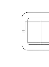
DESIGN CONSIDERATIONS
Below we have outlined some basic design best practices and tips which should be considered and implemented in any enclosure design. Some of these practices are more important when designing specifically for the injection moulding process, however all should be used for best part design.
In most cases, form should follow function. The best designs usually use pure geometric shapes, forming features around fixed constraints and functional aspects of the design.
1. AESTHETIC


2. MATING PARTS
Consideration of how parts will mate is critical. Its is rarely beneficial to have parts simply butting up to one another. This visually looks weak and functionally offers poor ingress protection.
A better design would be to design a lap joint into the parts. This offers improved ingress protection and offers a location feature for the parts. A purposeful split line can also be designed into the lap joint to break up the face.


3. USE OF RIBS
Ribs are used to add strength to designs, offering support to bosses and other features. To minimise warping during 3D printing and ensuring successful injection moulding, wall thicknesses must be carefully controlled. Ribs can be used to support these walls.
Furthermore, during the injection moulding process, ribs are used to improve flow.

4. PERSONALISATION
One advantage of bespoke enclosure design is personalisation. Logos or other information can be embossed or debosssed into the part at no additional cost.
Alternatively, these can be printed onto the enclosure using the silkscreen printing process and a post process.

5. FASTENER DESIGN
Bosses are used to house a fixing. Whether this is a thread forming screw or a threaded insert, the boss design and placement of the bosses should be carefully controlled to suit the specific fixing.
Usually, design detail is added to hide fixings flush inside the moulding. Incorrect boss design will ultimately result in bosses becoming weakened and failing during use.


6. WALL THICKNESS
Design rules should be closely followed to ensure parts are formed successfully. This is particulary important for injection moulded components as failure to control this will result in parts warping or sink marks where material has cooled at different rates. As a rule, internal walls such as ribs should be 2/3rd's the thickness of the general wall thickness.
Using fillets at the base of walls and ribs will further increase part strength and ensure successful moulding.

7. DRAFT
Draft is not required for 3D printing however is critical for mass production processes such as injection moulding and vacuum forming. Additional draft is required for deeper faces and faces with texture. Deep cores should be avoided and designed out where possible.
Failure to add draft will result in parts getting stuck on the tool during pass production.

8. UNDERCUTS
As a rule, undercuts should be avoided for injection moulding. Using more advanced tooling processes undercuts are possible they cannot be avoided. Please feel free to discuss your advanced tooling queries with us.
